Table of
Contents
0. Introduction
The aim of this tutorial is to show how to use
UML in "real" software development environment.
1. Elevator Problem
A product is to be installed to control elevators in a building with
m floors. The problem concerns the logic required to move elevators between
floors according to the following constraints:
-
Each elevator has a set of m buttons, one for each floor. These illuminate
when pressed and cause the elevator to visit the corresponding floor. The
illumination is canceled when the elevator visits the corresponding floor.
-
Each floor, except the first floor and top floor has two buttons, one to
request and up-elevator and one to request a down-elevator. These buttons
illuminate when pressed. The illumination is canceled when an elevator
visits the floor and then moves in the desired direction.
-
When an elevator has no requests, it remains at its current floor
with its doors closed.

2. Unified Modeling Language
UML is a modeling language that only specifies semantics and notation
but no process is currently defined. Thus, we decided to do the analysis
as follows;
-
Use Case Diagram
-
Class Diagram
-
Sequence Diagram
-
Collabration Diagram
-
State Diagram
3. Analysis
3.1. Use case diagram
Use case description:
-
A generalized description of how a system will be used.
-
Provides an overview of the intended functionality of the system.
-
Understandable by laymen as well as professionals.
Use Case Diagram:

Elevator basic scenario that can be extracted from Use Case Diagram:
-
Passenger pressed floor button
-
Elevator system detects floor button pressed
-
Elevator moves to the floor
-
Elevator doors open
-
Passenger gets in and presses elevator button
-
Elevator doors closes
-
Elevator moves to required floor
-
Elevator doors open
-
Passenger gets out
-
Elevator doors closes
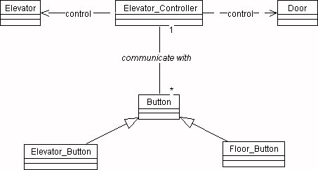
3.2. Class Diagram
Class diagrams show the static structure of the object, their internal
structure, and their relationships.
Class diagram:

3.3. State diagram
A state diagram shows the sequences of states an object goes through
during it's life cycle in response to stimuli, together with its responses
and actions.
4. Design
The design phase should produce the detailed class diagrams, collaboration
diagrams, sequence diagrams, state diagrams, and activity diagram. However,
the elevator problem is too simple for an activity diagram. Thus, we are
not using an activity diagram for the elevator problem.
4.1. Sequence Diagram
A sequence diagram and collaboration diagram conveys similar information
but expressed in different ways. A Sequence diagram shows the explicit
sequence of messages suitable for modeling a real-time system, whereas
a collobration diagram shows the relationships between objects.
Sequence Diagrams:
 Sequence Diagram for Serving Elevator Button
 Sequence Diagram for Serving Door Button
4.2. Collaboration diagram
-
Describes the set of interactions between classes or types
-
Shows the relationships among objects
Collabration diagrams:
 Collabration Digaram for Serving Elevator Button
 Collabration Digaram for Serving Door Button
5. Detail Design
5.1. Detail Class Diagram

5.2. Detail Operation Description
Module Name
Elevator_Control::Elevator_control_loop
Module Type
Method
Input Argument
None
Output Argument
None
Error Message
None
File Access
None
File Change
None
Method Invoke
button::illuminate, button::cancel_illumination,
door::open, door::close, elevator::move, elevator::stop
Narative
5.3. Pseudo-Code
void elevator_control (void)
{
while a button has been pressed
if button not on
{
button::illuminate;
update request list;
}
else if elevator is moving
up
{
if there is no request to stop at floor f
Elevator::move one floor up;
else
}
6. Acknowledgement
This example was developed for topic in software
engineering in Vanderbilt University
by myself and my best friends:
